
Cambria Standalone Installation Guide
- The purpose of this guide is to provide a walkthrough of the process of setting up a Cambria Standalone kiosk for use with the Versatile Credit, Inc. cascade.
- This guide is intended for the personnel responsible for setting up the kiosk.
- If you require any assistance past what this guide provides, please contact Versatile Credit Customer Support
- Email: support@versatilecredit.com
- Phone: 866-803-3369
- Website: versatilecredit.com (Contact Us)
Before You Begin
Before beginning the kiosk installation, be sure that you have the following:
- The Cambria Standalone Kiosk (shipped on a pallet)
- A Power Drill W/ Phillips Head Screw Bit - Figure A
- A Utility Knife - Figure B
Two People - Versatile Credit, Inc. recommends having two people install as the kiosk unit is both heavy and bulky


After Installation
After you install the kiosk, it must be configured for use. Please refer to the Cambria Standalone Configuration Guide for instructions on configuring the kiosk.
Step-by-Step Guide
Step 1 - Unpacking
The first step in installing the kiosk is unpacking it and removing the shipping material. The kiosk ships strapped to a pallet with protective cardboard and shrink wrapping.
- Using a utility knife, carefully cut the shrink wrap. After cutting the shrink wrap, it can be easily removed and discarded.
- Remove and discard the protective foam pieces and display packaging materials.
Unscrew the screws on the wooden planks holding the kiosk in place (Figure A.)


Step 2 - Setting Up the Kiosk
Slightly lift/tilt the kiosk and pull the power strip cord through the hole at the bottom of the enclosure (Figure B.)

- Plug the power strip cord into a standard wall power outlet.
- If the kiosk will be connected to the network via ethernet, unscrew the two screws that lock the display bracket located behind the display.
The ethernet cable must be routed from the bottom of the kiosk through the openings in the display bracket, as shown in Figure C.


Step 3 - Installing the Printer Paper
On the left side of the printer, press and slide the latch to open the lid. (Figure D)

- Flip the lid open.
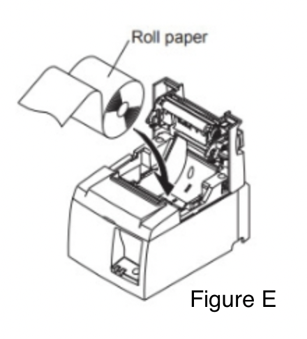
- Place the paper roll in the printer with the loose paper coming from under the roll towards the front of the printer, as shown in Figure E.
Two rolls of thermal paper are included in the Accessory Box included with the kiosk (" Please Open This First" box)
Once the thermal paper is installed, close the lid. The receipt paper will advance and trim the excess paper. (Figure F & G)


Appendix A - Detailed Diagram for Display Cable Connections
The following diagram (Figure H) illustrates the cables on the display's back. Additionally, it indicates how each cable must be routed and connected.
